Project Introduction
Project Title
AeroEdu is an innovative educational platform designed to make aerospace engineering accessible, interactive, and engaging for students and enthusiasts. The project brings together essential concepts, tools, and resources in a single, user-friendly portal.
Problem Statement
Many students and enthusiasts face challenges in accessing a unified, interactive, and offline-friendly resource for aerospace engineering basics. Existing materials are often scattered, require constant internet access, or lack engaging features. AeroEdu addresses these issues by providing:
- Unified Platform: All essential aerospace topics and tools in one place.
- Interactive Features: Calculators, quizzes, and AI tools for active learning.
- Offline Capability: Full access to content and tools without internet dependency.
- User-Friendly Design: Intuitive navigation and visually appealing layout for all users.
By bridging these gaps, AeroEdu empowers learners to master aerospace fundamentals efficiently and enjoyably.
Unit I: Basics of Flight Vehicles
- Ancient Myths: Stories like Icarus and Daedalus show early human fascination with flight.
- 1783: First manned hot air balloon flight by the Montgolfier brothers in France.
- Late 1800s: Glider experiments by Otto Lilienthal and others.
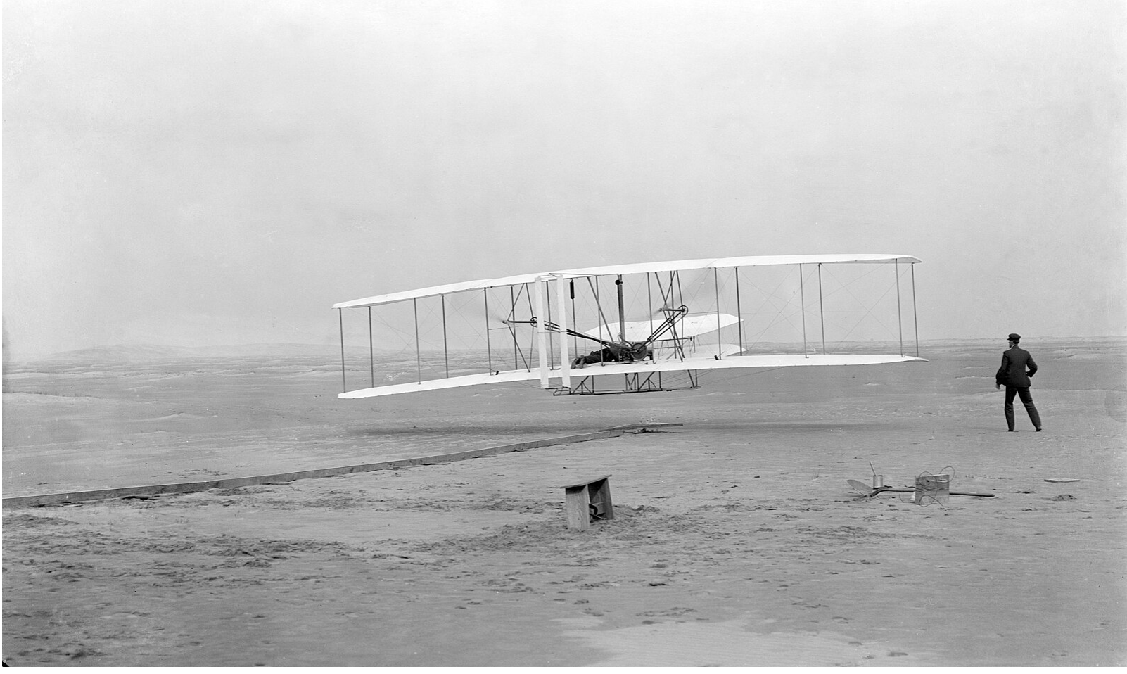
- 1903: Wright brothers achieve first powered, controlled flight at Kitty Hawk.
- 1914–1918: World War I accelerates aircraft development.
- 1930s–40s: Introduction of all-metal aircraft, jet engines, and helicopters.
- 1957: Sputnik 1 launches the space age.
- 1969: Apollo 11 lands humans on the Moon.
- Modern Era: Supersonic jets, commercial airliners, reusable rockets (SpaceX).
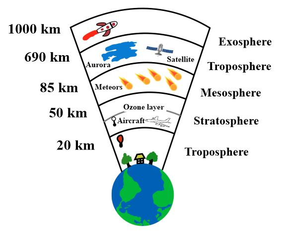
The International Standard Atmosphere (ISA) is a model that defines average atmospheric properties (temperature, pressure, density) at various altitudes. It is used for aircraft design, performance calculations, and calibration.
- Sea Level: 15°C, 101325 Pa, 1.225 kg/m³
- Troposphere: Up to 11,000 m, temperature decreases with altitude
- Stratosphere: 11,000–20,000 m, temperature nearly constant
- Applications: Used in flight planning, altimeter calibration, and performance charts
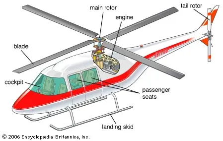
Modern aircraft and helicopters are made up of several key components, each serving a specific function for flight and control.
- Fuselage: Main body, holds crew, passengers, and cargo
- Wings/Rotors: Generate lift (fixed-wing or rotary-wing)
- Empennage: Tail assembly for stability and control
- Propulsion: Engines or rotors for thrust
- Landing Gear: Supports aircraft on ground
Unit II: Aircraft Aerodynamics
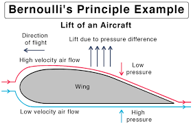
Bernoulli's theorem explains how pressure and velocity of a fluid (like air) are related. In aerodynamics, it helps explain how wings generate lift:
- As air flows over the curved upper surface of a wing, it speeds up, causing pressure to drop (Bernoulli's principle).
- The higher pressure below the wing pushes up, creating lift.
- Lift is also influenced by angle of attack and airfoil shape.
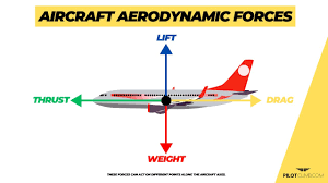
Aircraft experience several aerodynamic forces:
- Lift: Upward force generated by wings due to pressure difference.
- Drag: Resistance to motion through air. Two main types:
- Parasite Drag: Due to shape, skin friction, and interference (increases with speed).
- Induced Drag: Caused by lift generation (decreases with speed).
- Thrust: Forward force from engines.
- Weight: Downward force due to gravity.
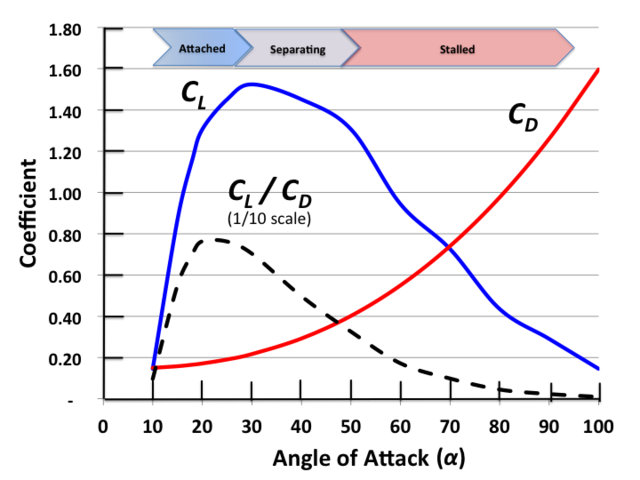
Aerodynamic coefficients quantify how effectively a shape generates lift or drag:
- Lift Coefficient (Cl): Indicates lift produced at a given angle of attack and shape.
- Drag Coefficient (Cd): Indicates drag produced by the shape and surface.
- Both are used in the lift and drag equations to calculate forces.
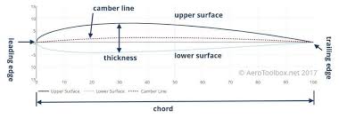
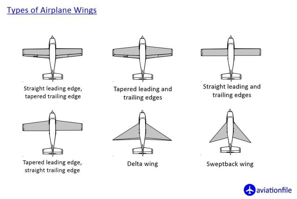
Airfoils and wings come in various shapes, each with unique aerodynamic properties:
- Airfoil Nomenclature: Leading edge, trailing edge, chord, camber, thickness, etc.
- Wing Planforms: Rectangular, tapered, swept, delta, elliptical.
- Shape affects lift, drag, and stall characteristics.
Unit III: Propulsion & Space Mechanics
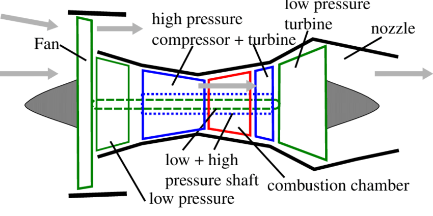
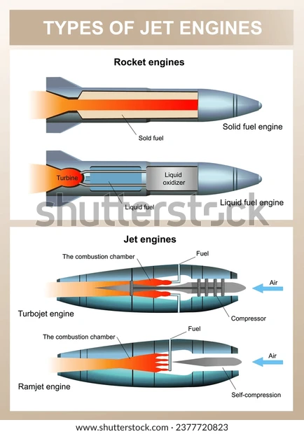
Jet engines are the primary propulsion systems for modern aircraft. There are several types:
- Turbojet: Simple jet engine, air is compressed, mixed with fuel, combusted, and expelled for thrust.
- Turbofan: Most common in airliners, uses a large fan to move more air for greater efficiency and quieter operation.
- Turboprop: Jet engine drives a propeller, efficient at lower speeds.
- Ramjet/Scramjet: No moving parts, operate at very high speeds (supersonic/hypersonic).
Rocket engines are used for spaceflight and high-speed missiles. Types include:
- Chemical Rockets: Use chemical propellants (liquid or solid) for thrust.
- Liquid Rockets: Fuel and oxidizer are stored separately and mixed in the engine.
- Solid Rockets: Propellant is a solid mixture, simple and reliable.
- Hybrid Rockets: Combine features of liquid and solid rockets.
- Electric/Ion Rockets: Use electric fields to accelerate ions, efficient for deep space.
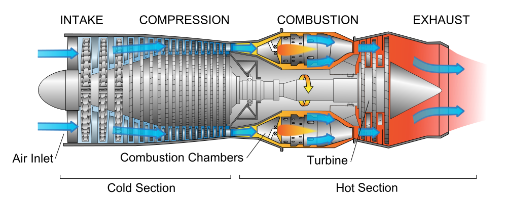
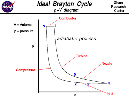
The Brayton cycle describes the thermodynamic process in jet engines:
- Air is compressed (increases pressure and temperature).
- Fuel is added and combusted at constant pressure (increases temperature).
- Hot gases expand through a turbine and nozzle, producing thrust.
- Efficiency depends on pressure ratio and temperature.
Orbital mechanics studies the motion of objects in space, governed by Kepler's Laws:
Description: Principles of propulsion systems and basics of space flight mechanics.
- Jet engines, Rocket engines
- Newton's laws in space
- Orbital motion basics
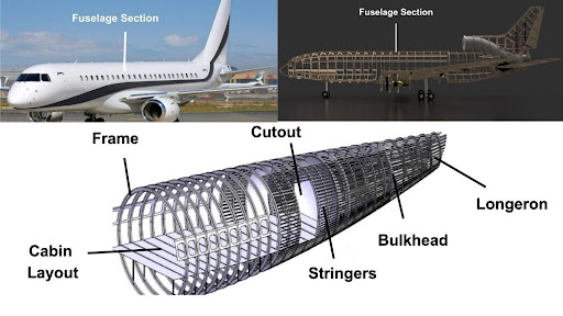
Unit IV: Aerospace Structures
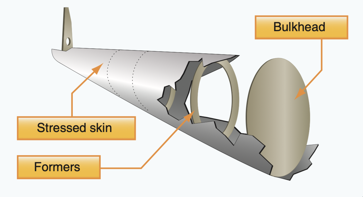
Aircraft structures are designed to be strong yet lightweight. Three main types are:
- Monocoque: The external skin supports most of the load. Simple but can be less damage-tolerant.
- Semi-Monocoque: Combines a load-bearing skin with internal frames and stringers. Most modern aircraft use this design for strength and redundancy.
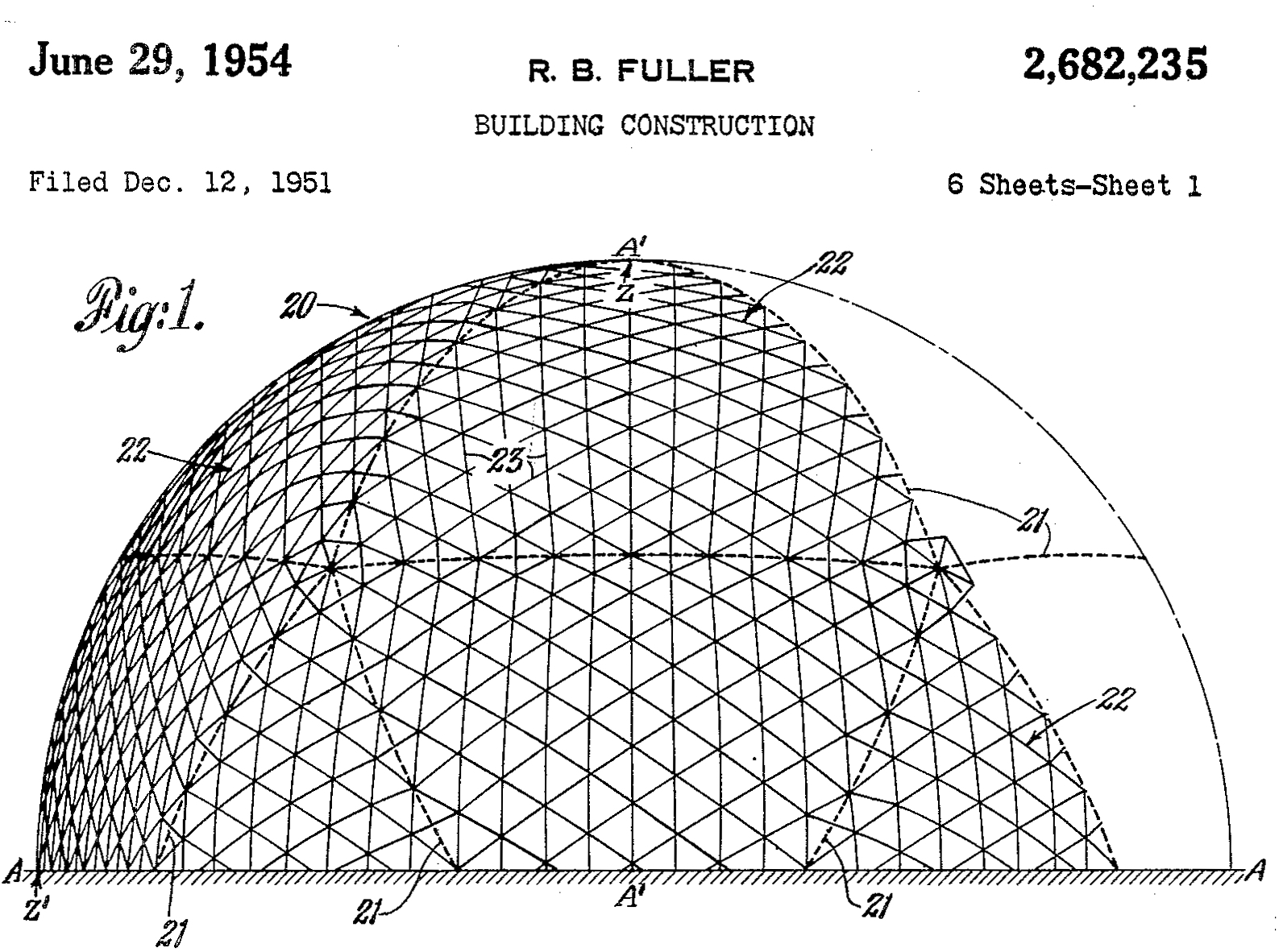
- Geodesic: Uses a lattice of intersecting structural members. Strong and damage-tolerant, used in some historic aircraft (e.g., Vickers Wellington).
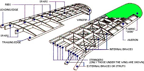
Wings and fuselages are built differently to handle specific loads:
- Wings: Designed to carry lift loads, often use spars, ribs, and skin. May include fuel tanks and control surfaces.
- Fuselage: Houses crew, passengers, and cargo. Built to handle bending, torsion, and pressurization loads.
- Both use lightweight, strong materials like aluminum alloys and composites.
Watch this video for a visual overview of aircraft structural elements and how they work together to ensure safety and performance.
Unit V: Systems & Instruments
Pitot tubes and air data systems are essential for measuring airspeed and other flight parameters:
- Pitot Tube: Measures dynamic pressure (difference between total and static pressure) to determine airspeed.
- Static Port: Measures ambient atmospheric pressure.
- Air Data Computer: Processes pitot and static data to provide airspeed, altitude, and vertical speed to instruments.
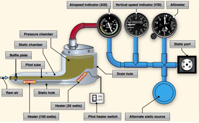
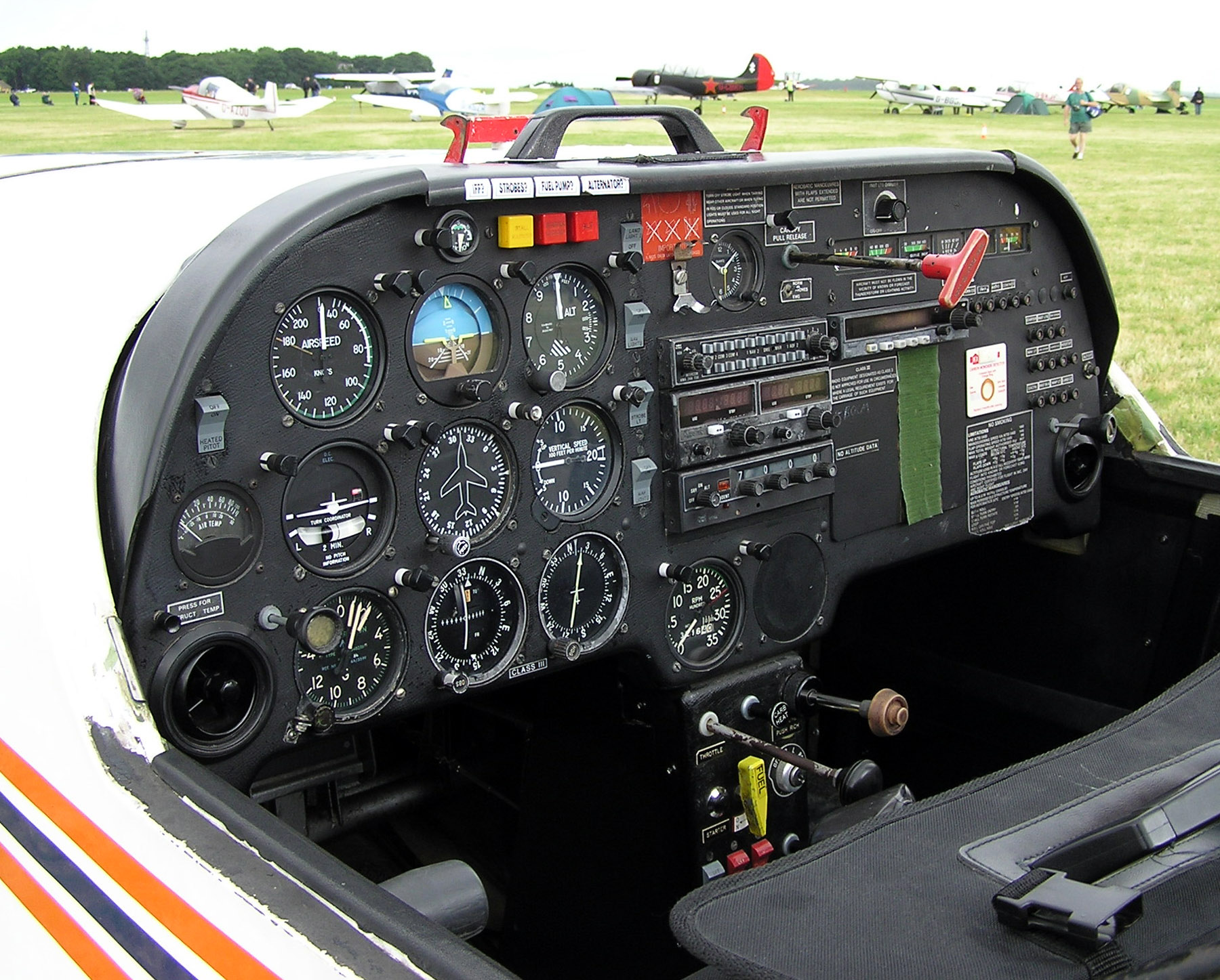
Altimeters and cockpit instruments provide pilots with critical flight information:
- Altimeter: Measures altitude using static pressure. Can be barometric or radar-based.
- Airspeed Indicator: Uses pitot-static system to show speed relative to air.
- Attitude Indicator: Shows aircraft orientation (pitch and roll) using gyroscopes.
- Other Instruments: Vertical speed indicator, heading indicator, turn coordinator, etc.
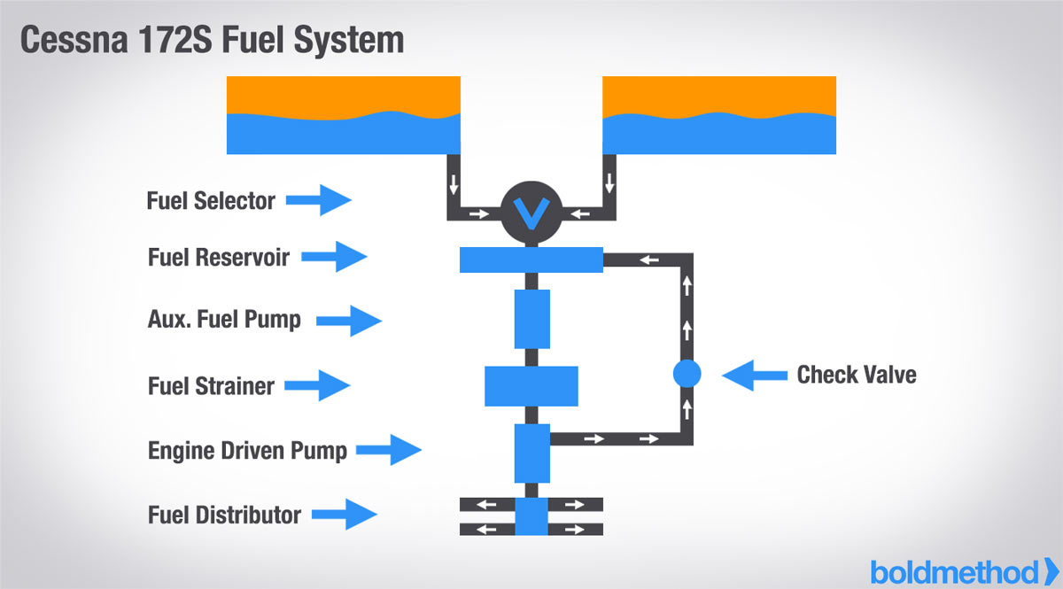
Modern aircraft use complex systems to manage fuel and operate controls:
- Fuel System: Stores and delivers fuel to engines. Includes tanks, pumps, valves, and filters.
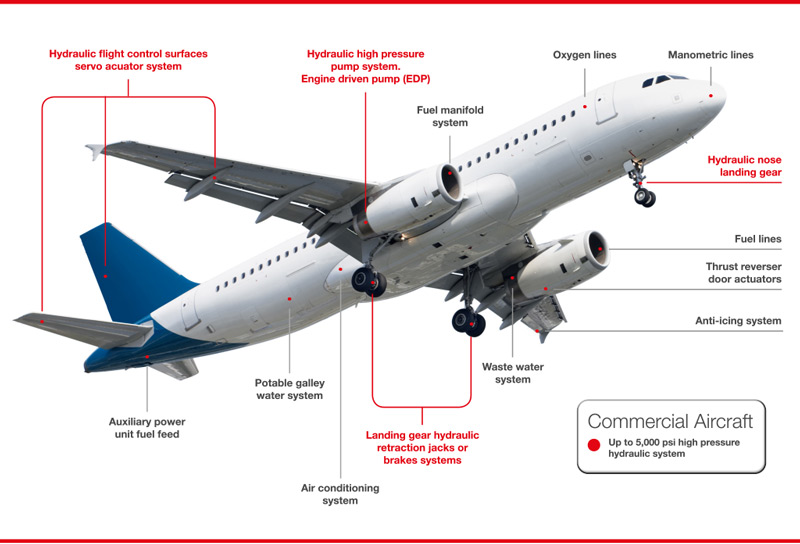
- Hydraulic System: Uses pressurized fluid to operate landing gear, brakes, flaps, and flight controls.
- Redundancy and safety features are built in to prevent failures.